What is UEFI?
UEFI (Unified Extensible Firmware Interface) is a modern boot system interface that replaces the traditional BIOS and is already widely used on both x86 and ARM architectures.
Traditional BIOS
The traditional BIOS refers to a standard interface that initializes hardware and loads the operating system bootloader when a computer starts. In other words, it is mainly responsible for detecting hardware functionality during startup and booting the operating system.
Traditional BIOS boot process:
When the computer is powered on, the hardware is set to start executing the BIOS. The BIOS is responsible for initializing the hardware, loading the bootloader, and then the bootloader loads and starts the operating system.
The BIOS is stored in erasable programmable read-only memory (EPROM). Given that BIOS seems so complete, why do we still need UEFI?
- The BIOS identifies hard drives initialized with a Master Boot Record (MBR). The MBR is located in the first sector (512 bytes) of the disk and contains:
- Boot code (446 bytes)
- Partition table (64 bytes)
- Signature: 0x55AA (2 bytes)
- Each partition table entry is 16 bytes, so there can be a maximum of four partitions. Also, the MBR partition table supports a maximum disk size of 2TB, and extended partitions are prone to errors. The BIOS cannot directly recognize file systems — the bootloader must implement its own file system driver.
- The BIOS is written in 16-bit assembly language, with 1MB memory addressing and interrupt execution. When booting with BIOS, the system runs in 16-bit real mode, meaning it can only directly access 1MB of memory. Complex switching is needed to enter the operating system.
- During startup, the BIOS must initialize hardware sequentially and cannot initialize devices in parallel. It also cannot verify the integrity of the operating system loader (such as GRUB).
These limitations of BIOS drove the development of UEFI.
Advantages of UEFI
Faster Boot Speed
- Parallel detection and initialization of hardware devices for faster startup
- Directly loads EFI applications without relying on the multi-stage boot process of MBR/VBR
- Built-in file system support allows direct reading of disk files without needing a bootloader
Support for Large-Capacity Disks and GPT Partitioning
- GPT supports 128 primary partitions and 64-bit addressing
Secure Boot
- Can verify the digital signature of the bootloader (
.efi)
Better Compatibility and Scalability
- Modular design with a driver model (such as
EFI_DRIVER) allowing dynamic loading of hardware drivers - Built-in network protocol stack supporting HTTP, HTTPS, and TFTP boot
- UEFI allows loading EFI programs from any FAT32 partition
Core Components of UEFI

BOOT SERVICE
Runs before the operating system is loaded. Boot services are terminated after the OS takes over system resources. Boot services provide the following functions:
- Manage memory: allocate and free memory, support different types of physical memory (such as conventional memory and reserved memory).
- Use timers to create and manage events, supporting asynchronous operations and timer functionality.
- Install, uninstall, and locate protocols, used for communication between drivers and applications.
- Load and start the operating system kernel or other executable images.
- Provide access to and control of hardware devices.
RUNTIME SERVICE
Provides a set of key functions during operating system runtime, including time management, variable services, and system reset:
- Time Management Get and set the system time.
- Variable Services Read and write UEFI variables (such as boot order, hardware configuration, etc.). UEFI variables are typically used to store system configuration information, for example:
- Boot Order (
BootOrder): Defines the boot device sequence. - Hardware Configuration: Stores hardware-related settings (e.g., network configuration, security settings).
- Boot Order (
- System Reset Supports system reboot or shutdown (on RISC-V architecture, reboot and shutdown are implemented through OpenSBI).
- Virtual Memory Management Manages virtual memory mapping during OS runtime.
Unlike boot services, runtime services remain available after the OS has loaded, offering an interface for the OS and applications to interact with the firmware.
OS LOADER
The OS Loader is part of the UEFI boot process.
It relies on UEFI Boot Services and Runtime Services to load the operating system kernel from a boot device (such as a hard drive, optical disc, or network), prepare its execution environment, and transfer control from the UEFI firmware to the operating system.
In Windows, the OS loader is bootmgfw.efi**, which is responsible for:**
- Loading the Windows kernel
- Preparing the Windows boot environment
In Linux, the OS loader is GRUB, which is responsible for:
- Loading the Linux kernel (
vmlinuz) and ramdisk (initrd) - Supporting multi-OS boot
- Providing a command-line interface for debugging and configuration
ACPI
ACPI (Advanced Configuration and Power Interface) defines the interface for power management and hardware configuration between the operating system and hardware.
It provides a standardized way for the OS to manage hardware resources, control power states, and support plug-and-play functionality.
ACPI not only defines power management functions but also provides an interface for hardware resource description and configuration.
ACPI Tables
ACPI tables are the core data structures of ACPI, used to describe hardware resources and power management information.
They are usually generated during the UEFI DXE (Driver Execution Environment) phase and passed to the OS by UEFI.
ACPI tables are stored in binary format, and the OS parses these tables to obtain hardware information.
SMBIOS
SMBIOS (System Management BIOS) is a standard defined by the DMTF (Distributed Management Task Force) to provide a standardized interface for the OS and management tools to obtain system hardware information.
It delivers hardware configuration, firmware version, motherboard details, and other data to the OS or management tools in a structured format.
SMBIOS data tables are generated by UEFI and stored in system memory, and the OS can access them through the system table.
The operating system or management tools can access the SMBIOS table in the following ways:
- System Table In the kernel, use
EFI_SYSTEM_TABLEto obtainEFI_CONFIGURATION_TABLE, and then locate the address of the SMBIOS table. - Operating System Users can query SMBIOS data using tools (such as
dmidecode) to obtain hardware information. - System Management Tools Standards like IPMI and Redfish use SMBIOS data to monitor hardware status, diagnose faults, and manage system resources.
UEFI Boot Process
UEFI consists of six main boot stages, each playing a critical role in the platform’s startup and initialization process.
All these steps together are commonly referred to as Platform Initialization (PI).
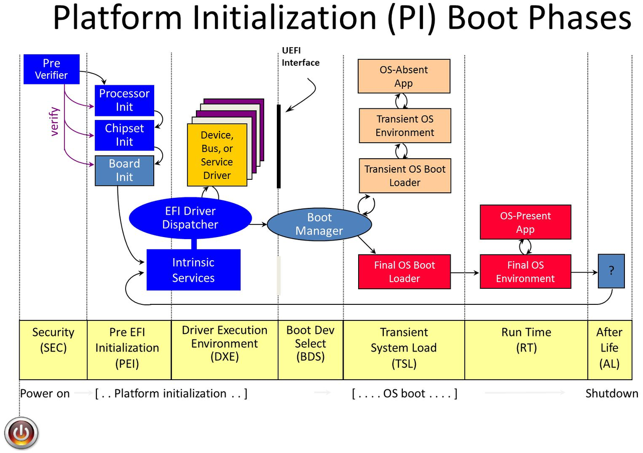
1. Security Phase (SEC)
This is the first stage in the UEFI boot process. It primarily initializes a temporary memory area that serves as the root of the system’s chain of trust and provides necessary information to the Pre-EFI Initialization (PEI) phase.
This root of trust ensures that any code executed during the Platform Initialization (PI) process is cryptographically verified (i.e., digitally signed), establishing a secure boot environment.
2. Pre-EFI Initialization Phase (PEI)
The second stage of the boot process, which uses only the CPU’s current resources to schedule Pre-EFI Initialization Modules (PEIMs).
These modules handle critical startup tasks such as memory initialization and also allow control to be passed to the Driver Execution Environment (DXE).
3. Driver Execution Environment (DXE)
Most system initialization occurs during the DXE phase.
By the time DXE runs, the memory needed for DXE operations has been allocated and initialized during PEI.
When control is handed over to DXE, the DXE dispatcher is activated.
The dispatcher is responsible for loading and executing hardware drivers, runtime services, and any boot services required for OS startup.
4. Boot Device Selection (BDS)
Once all DXE drivers have run, control passes to the BDS phase.
This phase initializes console devices and any remaining required hardware.
It then loads and executes the selected boot option to prepare for the Transient System Load (TSL) phase.
5. Transient System Load (TSL)
This phase bridges the gap between boot device selection and transferring control to the OS.
At this point, an application such as the UEFI shell may be invoked, or (more commonly) a bootloader runs to prepare the final OS environment.
The bootloader typically terminates UEFI boot services by calling ExitBootServices().
However, the OS itself can also perform this, for example the Linux kernel with CONFIG_EFI_STUB.
6. Runtime (RT)
This is the final phase when the OS takes control of the system.
Although UEFI boot services are no longer available, UEFI runtime services remain accessible to the OS, such as querying and writing variables in NVRAM.